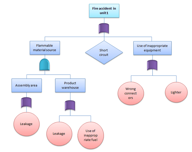
Before you can prevent future failures, you must first determine the root cause of the problem[cite: 11]. Otherwise, it is not a matter of if the failure will happen again, but simply a matter of time[cite: 11]. Fault Tree Analysis is a method utilized to discover the root cause of an issue, enabling the identification and analysis of the fundamental reasons before an equipment failure occurs[cite: 11].
The Development of Fault Tree Analysis
The Fault Tree Analysis method was first proposed in 1961 by Watson and Mearns of Bell Telephone Laboratories in the United States, where it was applied to analyze the Minuteman missile launch control system[cite: 11]. Subsequently, engineers at Boeing developed computational programs for the FTA method, marking its entry into the aerospace sector centered around Boeing[cite: 11].
In 1974, the United States Atomic Energy Commission published a 3,000-page report titled the "Reactor Safety Study"[cite: 11]. This report was compiled after two years of research by a safety group comprising 60 experts, led by Professor Norman Rasmussen of the Massachusetts Institute of Technology (MIT)[cite: 11]. The report evaluated the risks of nuclear power plants using Event Tree (ET) and Fault Tree Analysis methods targeting 100 commercial light-water reactor nuclear power plants in the US[cite: 11]. This significantly advanced the application of FTA[cite: 11]. The publication of this report elicited a massive response from various sectors and is regarded as a major milestone in the developmental history of FTA[cite: 11].
What is a Fault Tree?
A fault tree, also known as an error tree, is a specialized inverted tree-like logical causal relationship diagram[cite: 11]. It primarily employs event symbols, logic gate symbols, and transfer symbols to represent the causes of an accident or fault event and their logical relationships in a logic tree diagram[cite: 11].
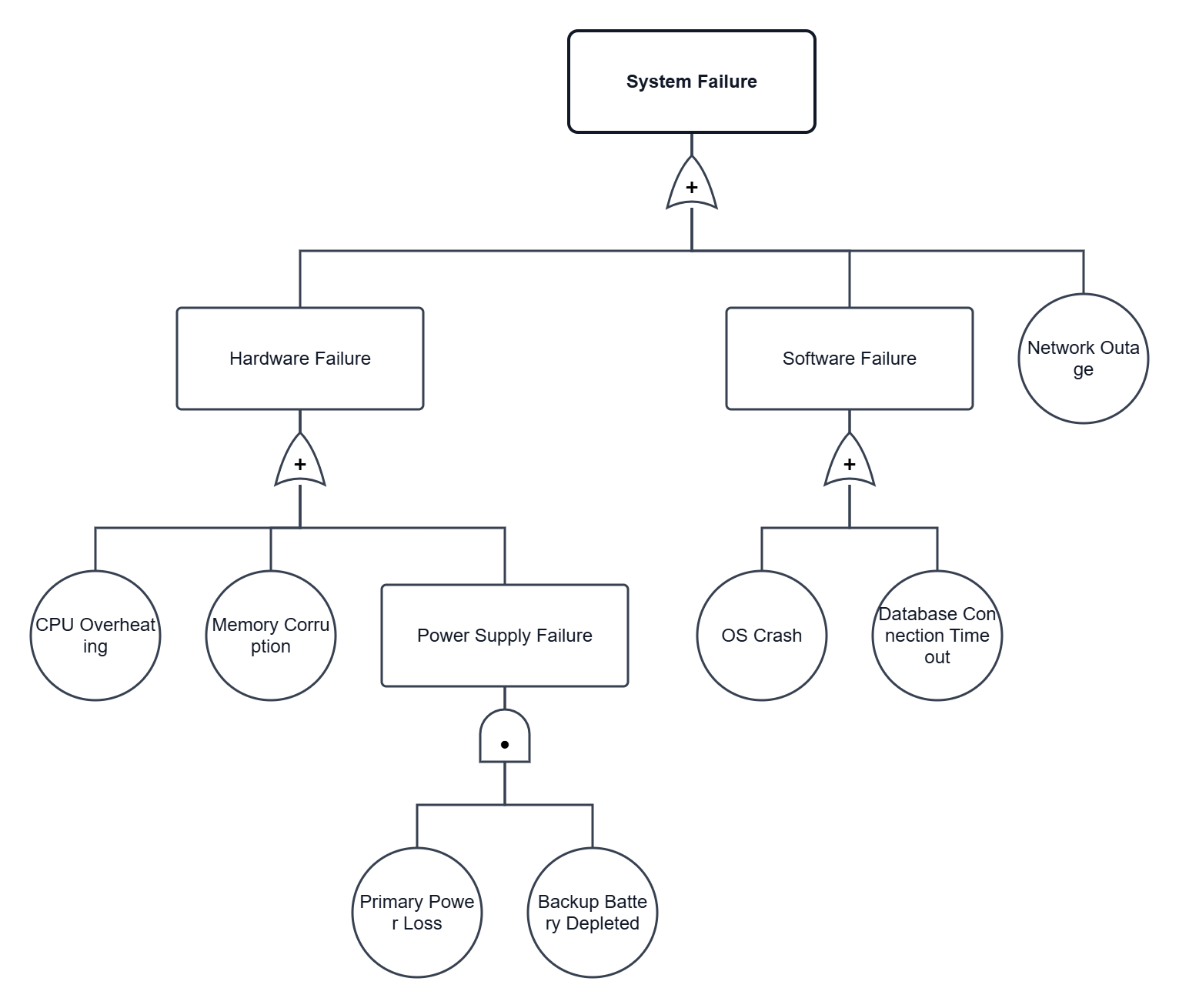
IEC 61025:2006 delineates the methodology of fault tree analysis and provides guidelines for its application[cite: 11]. It simultaneously establishes suitable assumptions, events, and failure modes, and provides an explanation of identification rules and symbols[cite: 11].
Events and Their Symbols in Fault Trees
The occurrence of a condition or action is termed an event[cite: 11].
| Event Type | Event Symbol | Description |
|---|---|---|
| Basic Event | 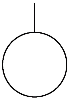 |
Circle: Represents a basic event, which is the originating root fault that requires no further, or cannot be further, investigated[cite: 11]. |
| Resultant Event |  |
Rectangle: Represents a top event or an intermediate event, which is a fault or consequence requiring further analysis[cite: 11]. |
| Undeveloped Event | 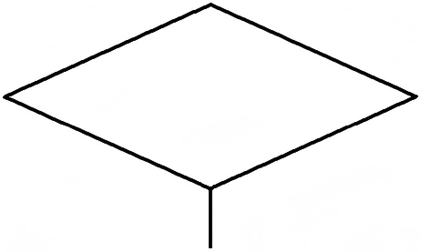
|
Diamond: Represents an omitted event, indicating an event not further investigated due to a lack of information or lack of significance[cite: 11]. |
| Switch Event |  |
House: Represents a normal event or conditional switch event, which inevitably occurs or exists in a specific state under normal circumstances[cite: 11]. |
| Conditioning Event | 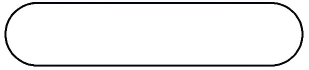
|
Ellipse: A conditional restriction that limits a logic gate or influences the occurrence of a specific event[cite: 11]. Usually paired with an inhibit gate[cite: 11]. |
Logic Gates and Their Symbols in Fault Trees
In fault tree analysis, logic gates strictly describe the logical causal relationships between events[cite: 11].
| Logic Gate | Logic Symbol | Description |
|---|---|---|
| AND Gate | 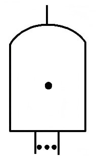 |
Indicates that the output event occurs only if all input events occur[cite: 11]. |
| OR Gate | 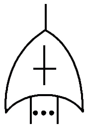 |
Indicates that the output event occurs if at least one input event occurs[cite: 11]. |
| NOT Gate | 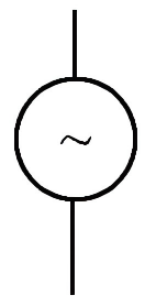 |
Indicates that the output event is the mutually exclusive opposite of the input event[cite: 11]. |
| Priority AND Gate | 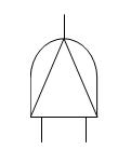
|
Indicates that the output event occurs only if the input events occur in a specified sequence[cite: 11]. |
| Voting Gate | 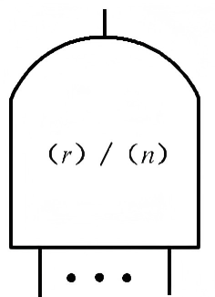 |
Indicates that the output event occurs only if *k* or more out of *n* input events occur[cite: 11]. |
| Exclusive OR Gate | 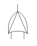
|
Indicates that the output event occurs only if exactly one single input event occurs[cite: 11]. |
| Inhibit Gate | 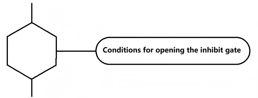 |
Indicates that the occurrence of the input event leads to the output event only when the conditioning event occurs[cite: 11]. |
Transfer Symbols in Fault Trees
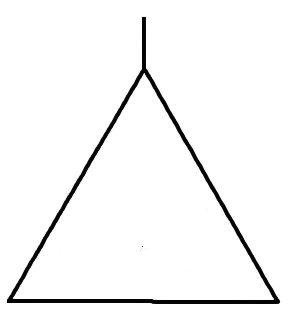
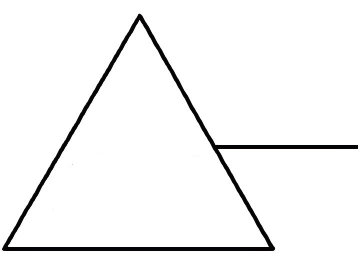
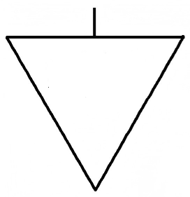
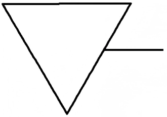
Transfer symbols are established to avoid repetition during drafting and to keep the diagram concise[cite: 11].
| Transfer Type | Transfer Symbol | Description |
|---|---|---|
| Identical Transfer Symbol |
|
Identical transfer symbols are used to indicate the location of a subtree[cite: 11]. |
| Similar Transfer Symbol |
|
Similar transfer symbols are used to indicate the location of a similar subtree[cite: 11]. |
It becomes apparent that various gates inherently involve Boolean algebra, meaning fault trees can be simplified through Boolean operations[cite: 11]. A fault tree utilizes the previously described event symbols, logic gate symbols, and transfer symbols to depict the causal relationships among various events within a system[cite: 11]. The input events of a logic gate are the "causes" of the output event, and the output event of a logic gate is the "effect" of the input events[cite: 11].
What Can Fault Tree Analysis Accomplish?
- Understand the relationship between the top-level event and the underlying undesired states[cite: 11].
- Demonstrate the degree to which a system complies with system safety/reliability specifications[cite: 11].
- Prioritize the various causes resulting in the top-level event: establish a list of critical equipment/components/events based on different weighted measurement methods[cite: 11].
- Monitor and control the safety performance of complex systems (e.g., Can a specific aircraft fly safely when fuel valve x malfunctions? How long can the aircraft fly under these conditions?)[cite: 11].
- Minimize and optimize resource requirements[cite: 11].
- Assist in system design[cite: 11]. Fault tree analysis can serve as a design tool to create requirements for outputs or lower-level modules[cite: 11].
- Act as a diagnostic tool to identify and correct causes leading to the top-level event, aiding in the creation of diagnostic manuals or procedures[cite: 11].